Connecting a passive TAP: Difference between revisions
No edit summary |
No edit summary |
||
| (31 intermediate revisions by the same user not shown) | |||
| Line 2: | Line 2: | ||
== Introduction == | == Introduction == | ||
Passive Fiber Optic TAPs require little or no configuration. While cabling the network - and site ports is straight forward, the cabling between the TAP output and the NETSCOUT Accelerator NIC is somewhat special. | |||
| | ||
| Line 10: | Line 10: | ||
| | ||
== | {{#invoke:Message box|ambox |type=content|text=A single passive TAP could add 3dB of optical loss to the link it is inserted in. Make sure you have a sufficiently lage optical power budget before inserting the TAP.}} | ||
| |||
{{#invoke:Message box|ambox |type=content|text=Inspect and clean all optical connectors and bulk heads before making a connection.}} | |||
| |||
{{#invoke:Message box|ambox |type=content|text=Passive TAPs are direction sensitive! Make sure to respect the fiber poloarity while connecting. when Rx/Tx are reversed on both ports A and B, the tapped link will still become active, however, the bleed-off won't work.}} | |||
| | ||
=== | === LC SM/MM HD Fiber TAP === | ||
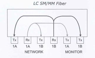
The label on the tap indicated where the light should arrive (Rx) and where it will be transmitted (Tx). | |||
==== TAP internal wiring: ==== | |||
| | ||
[[File:TAPInternalCabling.png|border|center|400px|TAPInternalCabling.png]] | |||
==== Y-cable ==== | |||
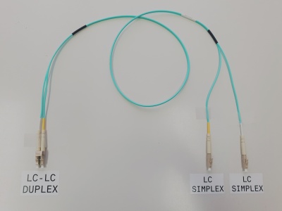
The two fibers of the duplex LC-LC output of the TAP - indicated with "monitor 1A and 1B" - are used for transmission. | |||
To connect to the NETSCOUT Accelerator NIC, you need a LC-LC-duplex to 2x LC-simplex Y-cable. It is very simple to make a cable like this from a standard duplex fiber optic patch cord: | |||
| | ||
[[File:LCLCFanOut.jpg|border|center|400px|LCLCFanOut.jpg]] | |||
| | ||
==== Connecting the TAP to the NETSCOUT Accelerator NIC ==== | |||
Both LC-simplex connectors of the Y-cable must be connected to the input (Rx) of two ports on the NETSCOUT Accelerator NIC on the rear of the appliance. The ports are numberd from top to bottom. Some appliances (like the PMA-2XX) have the card rotated 90° clockwise. In that case nubers start from right to left. If not fully used, connect the lowest port numbers first. | |||
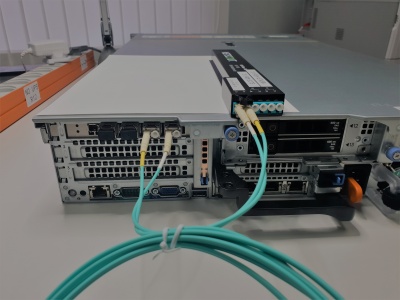
The following picture is showing the TAP - situated on top of the appliance - while the output is connected with a Y-cable to the first and second interface (equiped with 10GBASE-SX SFP+) of the NETSCOUT Accelerator NIC. The TAP is not yet brought in line. | |||
| | ||
[[File:TAPConnectNIC.jpg|border|center|400px|TAPConnectNIC.jpg]] | |||
| | ||
=== Port aggregation === | |||
An aggregate must be created from the two connected ports. Ask your COMCERT Engineer to configure a Port Aggregate or read the Agent Configuration Utility for CDM/ASI Administration Guide carefully for details on how to create a Port Aggregate. | |||
Latest revision as of 16:44, 23 December 2022
Introduction
Passive Fiber Optic TAPs require little or no configuration. While cabling the network - and site ports is straight forward, the cabling between the TAP output and the NETSCOUT Accelerator NIC is somewhat special.
Solution
| A single passive TAP could add 3dB of optical loss to the link it is inserted in. Make sure you have a sufficiently lage optical power budget before inserting the TAP. |
| Inspect and clean all optical connectors and bulk heads before making a connection. |
| Passive TAPs are direction sensitive! Make sure to respect the fiber poloarity while connecting. when Rx/Tx are reversed on both ports A and B, the tapped link will still become active, however, the bleed-off won't work. |
LC SM/MM HD Fiber TAP
The label on the tap indicated where the light should arrive (Rx) and where it will be transmitted (Tx).
TAP internal wiring:

Y-cable
The two fibers of the duplex LC-LC output of the TAP - indicated with "monitor 1A and 1B" - are used for transmission.
To connect to the NETSCOUT Accelerator NIC, you need a LC-LC-duplex to 2x LC-simplex Y-cable. It is very simple to make a cable like this from a standard duplex fiber optic patch cord:

Connecting the TAP to the NETSCOUT Accelerator NIC
Both LC-simplex connectors of the Y-cable must be connected to the input (Rx) of two ports on the NETSCOUT Accelerator NIC on the rear of the appliance. The ports are numberd from top to bottom. Some appliances (like the PMA-2XX) have the card rotated 90° clockwise. In that case nubers start from right to left. If not fully used, connect the lowest port numbers first.
The following picture is showing the TAP - situated on top of the appliance - while the output is connected with a Y-cable to the first and second interface (equiped with 10GBASE-SX SFP+) of the NETSCOUT Accelerator NIC. The TAP is not yet brought in line.

Port aggregation
An aggregate must be created from the two connected ports. Ask your COMCERT Engineer to configure a Port Aggregate or read the Agent Configuration Utility for CDM/ASI Administration Guide carefully for details on how to create a Port Aggregate.