Connecting a passive TAP: Difference between revisions
No edit summary |
No edit summary |
||
| Line 40: | Line 40: | ||
| | ||
==== Connecting the TAP to the NETSCOUT | ==== Connecting the TAP to the NETSCOUT Accelerator NIC ==== | ||
Both LC-simplex connectors | Both LC-simplex connectors of the Y-cable must be connected to the input (RX) of two SFP/SFP+ ports on the NETSCOUT Accelerator NIC on the back of the appliance. The ports are numberd from top to bottom. In some servers (like the PMA-2XX), the card is 90° rotated clockwise. It is recommeded to use the lowest port numbers first. | ||
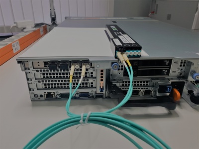
The following picture is showing the TAP - situated on top of the server - while its output is connected via a Y-cable to the first and second interface (SFP) on the server. | |||
| | ||
Revision as of 17:15, 15 July 2022
Introduction
Passive Fiber Optic TAPs require little or no configuration. While cabling the network - and site ports is straight forward, the cabling between the TAP output and the NETSCOUT Accelerator NIC is somewhat special.
Solution
| Inspect and clean if necessary all optical connectors and bulk heads before making a connection. |
| Passive TAPs are direction sensitive! Make sure to make RX and TX connections accordingly! |
LC SM/MM HD Fiber TAP
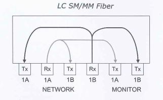
TAP internal cabling

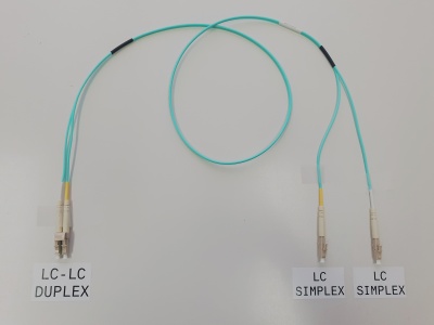
Y-cable
The two fibers of the duplex LC-LC output of the TAP - indicated with "monitor" - are both used for transmission.
To connect to the NETSCOUT Accelerator NIC, you need a LC-LC-duplex to 2x LC-simplex fan-out cable. It is very easy to make a cable like that.

Connecting the TAP to the NETSCOUT Accelerator NIC
Both LC-simplex connectors of the Y-cable must be connected to the input (RX) of two SFP/SFP+ ports on the NETSCOUT Accelerator NIC on the back of the appliance. The ports are numberd from top to bottom. In some servers (like the PMA-2XX), the card is 90° rotated clockwise. It is recommeded to use the lowest port numbers first.
The following picture is showing the TAP - situated on top of the server - while its output is connected via a Y-cable to the first and second interface (SFP) on the server.

Link aggregation
To analyze the date from the TAP correctly, you MUST create an aggregate that includes the two ports on the accelerator NIC connected to the TAP. In this example, those interfaces are if3 and if4. Ask our COMCERT Engineer to configure a aggregate for you or read the Agent Configuration Utility for CDM/ASI Administration Guide for details on how to do this.