Connecting a passive TAP
Introduction
Passive Fiber Optic TAPs require little or no configuration. While cabling the network - and site ports is straight forward, the cabling between the TAP output and the NETSCOUT Accelerator NIC is somewhat special.
Solution
| A single passive TAP could add 3dB of optical loss to the link it is inserted in. Make sure you have a sufficiently lage optical power budget before inserting the TAP. |
| Inspect and clean all optical connectors and bulk heads before making a connection. |
| Passive TAPs are direction sensitive! Make sure to make RX and TX connections accordingly! |
LC SM/MM HD Fiber TAP
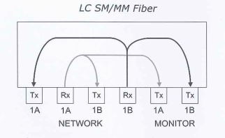
The label on the tap indicated where the light should arrive (Rx) and where it will be transmitted (Tx). Attention: when Rx/Tx are reversed on ports A andB, the link will still come up but the bleed-off won't work.
TAP internal wiring:

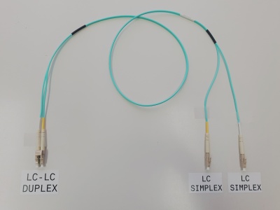
Y-cable
The two fibers of the duplex LC-LC output of the TAP - indicated with "monitor" - are both used for transmission.
To connect to the NETSCOUT Accelerator NIC, you need a LC-LC-duplex to 2x LC-simplex fan-out cable. It is very simple to make a cable like this from a standard (zip) fiber optic patch cord:

Connecting the TAP to the NETSCOUT Accelerator NIC
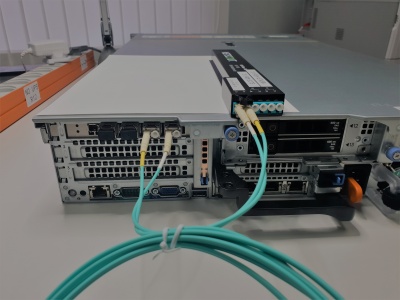
Both LC-simplex connectors of the Y-cable must be connected to the input (RX) of two SFP/SFP+ ports on the NETSCOUT Accelerator NIC on the back of the appliance. The ports are numberd from top to bottom. Some appliances (like the PMA-2XX) have the card rotated 90° clockwise. It is recommeded to start with the lowest port numbers.
The following picture is showing the TAP - situated on top of the appliance - while the output is connected with a Y-cable to the first and second interface (SFP+) of the NETSCOUT Accelerator NIC. The TAP is not yet brought in line.

Port aggregation
An aggregate must be created from the two connected ports. Ask your COMCERT Engineer to configure a Port Aggregate read the Agent Configuration Utility for CDM/ASI Administration Guide carefully for details on how to create a Port Aggregate.